
RANKINE CYCLE
An Idealized Thermodynamic Cycle
OVERVIEW
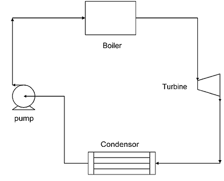
Most vapor power plants operate on the Rankine cycle. The Rankine cycle is a thermodynamic cycle—a sequence of processes that begins and ends at the same state—that takes heat from a fuel source and creates mechanical or electrical energy. The means for this heat transfer and work generation is called the ‘working fluid,’ and it is most often water (steam). For our purposes, we will be analyzing the Rankine cycle using water. The Rankine cycle for a fossil-fuel-powered vapor power plant is broken into four thermodynamic processes: compression, constant-pressure heating, expansion, and constant-pressure cooling (Reisel, 2015).
PRESSURE-VOLUME PLOT
The Figure on the left shows a Pressure versus Specific Volume diagram for the Rankine cycle. This diagram shows the different states of the fluid, along with the addition or rejection of work and heat. To explain more about each state:
State 1 is fully saturated since its point lies along the saturation curve.
State 2 is a compressed liquid, since its point lies on the left of the saturation curve.
State 3 is a superheated vapor since its point lies to the right of the saturation curve.
State 4 is a saturated fluid since its point lies within the saturation curve.
PROCESSES
We will go into explaining the four processes that occur in the Rankine cycle. For clarification purposes:
Process 1→ 2 is when water goes through the pump
Process 2→ 3 is when compressed water is heated in the boiler
Process 3→ 4 is when high pressured steam goes through the turbine
Process 4→ 1 is when steam from the turbine is sent to the condenser
We created the P-h diagram to the left to demonstrate pressure and enthalpy changes across each process, as well as the heat/work exchanges. Each process will be explained below in greater detail.
_edited.jpg)
PUMP
In process 1→2, water at a certain temperature and pressure is fed into the pump(s), and is compressed (temperature remaining constant) and sent to the boiler. This process takes work, but is adiabatic and therefore there is no heat transfer. Thus, net change in enthalpy of the process is simply due to the work input of the pump to compress the water. Because this is an input of work into the system, our enthalpy change is likewise negative. A feedwater pump from the Abbott Power Plant is shown to the left.

BOILER
In process 2→3, the compressed water is heated in the boiler until it evaporates completely. This corresponds to an increase in temperature, and a decrease in pressure; however, the volume of the boiler remains constant and thus no work is done. Therefore, for this process, net change in enthalpy is only due to the addition of heat. An addition of heat to the system is positive, which results in a positive change in enthalpy. The boiler of the Abbott Power Plant is to the left.

TURBINE
In process 3→4, the still-high-pressure and temperature steam is sent to the turbine, and expands through the turbine. Expansion in the turbine creates mechanical work in the rotation of the turbine. Work is done by the system, and no heat is lost in this expansion process. Therefore, the change in enthalpy is equal to the work done by the steam in the turbine. Enthalpy change is positive since work is done by the system. One of the Abbott Power Plant's turbines is shown on the left.

CONDENSER
In process 4→1, the steam from the turbine is sent to the condenser, where it exchanges heat with the cooling water and condensates. A heat transfer occurs, but no work is done because the volume of the condenser is constant. Therefore, change in enthalpy depends on heat transfer. Since heat is lost, our enthalpy change is negative. The condenser of the Abbott Power Plant is shown to the left.
